
NEET Physics Electromagnetic Induction Notes
Electromagnetic Induction
The phenomenon of the production of EMF across an electrical conductor in a changing magnetic field is called electromagnetic induction.
The magnetic flux through a surface is defined as,
\(\phi=\oint \overrightarrow{\mathrm{B}} \cdot \overrightarrow{\mathrm{A}}=\mathrm{BA} \cos \theta\) Where is the angle between a magnetic field and area vector.
Read And Learn More: NEET Physics Notes
Faraday’s Law of EMI
The magnitude of induced emf in a coil is equal to the rate of change of magnetic flux.
\(\text { i.e., } e=-\frac{d \phi}{d t}\)If there are N turns in the coil,
Electromagnetic Induction NEET Important Questions
\(e=-\frac{N d \phi}{d t}\)The negative symbol indicates that the induced emf opposes the change in flux.
Lenz’s Law
The direction of induced emf or current in the circuit is such that, it opposes the cause that produced it.
Lenz’s law is in accordance with the law of conservation of energy.
Motional EMF
- If a conducting rod of length is moving with a uniform velocity \(\overrightarrow{\mathrm{v}}\) perpendicular to a uniform magnetic field \overrightarrow{\mathrm{B}}, then the magnitude of induced emf in the rod is given by,
\(\mathrm{e}-\mathrm{B} / \mathrm{v}\) - If a rod is moving by making an angle with the direction of a magnetic field, the
\(\mathrm{e}=\mathrm{B} / \mathrm{v} \sin \theta\) - If a conductor starts sliding from the top of an inclined plane with the angle of inclination (θ) then,
\(\begin{aligned}
& \mathrm{e}=\mathrm{B} l v \sin (90-\theta) \\
& \Rightarrow \mathrm{e}=\mathrm{B} l v \cos \theta
\end{aligned}\)
Note:
Consider a conducting rod of length ‘l’ whose one end is fixed, is rotated about the axis passing through its fixed end and perpendicular to its length with constant angular velocity. The magnetic field ‘B’ is perpendicular to plane of the paper, then
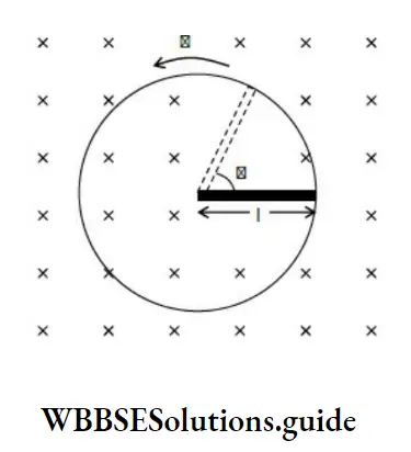
The induced emf across the ends of the rod is given by,
Faraday’s Law and Lenz’s Law NEET Questions with Solutions
\(\begin{aligned}&E_{\text {sut }}=\frac{1}{2} \mathrm{~B} / v=\frac{\mathrm{B} l}{2}(\omega /)\\
&\mathrm{E}_{\mathrm{sa}}=\frac{1}{2} \mathrm{~B} \omega \ell^2
\end{aligned}\)
Where \(‘ \omega^{\prime}=2 \pi f\)
Self Induction
The phenomenon in which emf is induced in one coil due to a change in current in the same coil is called self-induction.
w.k.t., \(\phi \propto I \text { or } \phi=LI\)
Where L is called the coefficient of self-induction or self-inductance of the coil.
The induced emf in the coil is given by
\(\mathrm{e}=-\frac{\mathrm{d} \phi}{\mathrm{dt}} \Rightarrow \mathrm{e}=-\mathrm{L} \frac{\mathrm{dI}}{\mathrm{dt}}\) \(\text { If } \frac{\mathrm{dI}}{\mathrm{dt}}=1 \mathrm{As}^{-1} \text {, then }|\mathrm{e}|=\mathrm{L}\)S.I. unit of L is Henry (H).
Dimensional formula of [L] = [ML2 T-2A-2]
Self-inductance of a long solenoid
Where N is the total number of turns, A is the area of the Cross section, and ‘l’ is the length of the solenoid.
Mutual Induction
The phenomenon in which emf is induced in one coil due to a change in current in the neighboring coil is called mutual induction.
Induced emf due to mutual induction is given by,
\(\mathrm{E}=-\mathrm{M} \frac{\mathrm{dI}}{\mathrm{dt}}\)Mutual Inductance of Two Long Co-Axial Solenoids
\(\mathrm{M}=\frac{\mu_0 \mathrm{~N}_1 \mathrm{~N}_2 \pi \pi_1^2}{l}\)Where, l is the length of the solenoids, N1 & N2 are the number of turns in the inner and outer solenoids respectively is the radius of the inner solenoid.
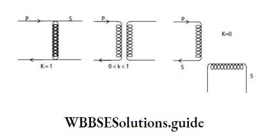
Relation Between M, L1 and L2
For two magnetically coupled coils
\(\mathrm{M}=\mathrm{k} \sqrt{\mathrm{L}_1 \mathrm{~L}_2}\)Where k is the coefficient of coupling or coupling factor.
\(\begin{gathered}\mathbf{k}=\frac{\text { Magnetic flux linked in secondary }}{\text { Magentic flux linked in primary }} \\
0 \leq \mathrm{k} \leq 1
\end{gathered}\)
NCERT Summary of Electromagnetic Induction for NEET
Combination of Inductors
If two coils of self inductances L1 and L2are in series and are far from each other, so that the mutual induction between them is negligible, then,
Ls = L1 + L2
If L1 and L2 are connected in parallel and if they are far from each other, then,
\(\frac{1}{L_p}=\frac{1}{L_1}+\frac{1}{L_2} \text { or } L_p=\frac{L_1 L_2}{L_1+L_2}\)Induced emf in a coil is given by,
\(\begin{aligned}& \mathrm{e}=\mathrm{NBA} \omega \sin \omega \mathrm{t} \\
& \mathrm{e}=\mathrm{e}_0 \sin \omega \mathrm{t}
\end{aligned}\)
Where, \(\mathrm{e}_0=\mathrm{NBA} \omega\) is the peak/maximum value of emf.
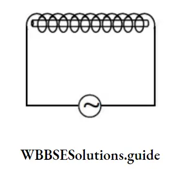
Choke coil
It is a device having high inductance and negligible resistance.
Chapter-wise Weightage for NEET Physics Electromagnetic Induction
It consists of thick copper (Cu) wire to reduce the resistance of the circuit and a soft iron core to improve the inductance of the circuit.
Transformer works on the principle of mutual induction.
The efficiency of a transformer is given by
\(\eta=\frac{\text { Output power }}{\text { Input power }}=\frac{V_S I_S}{V_D I_D}\)Application of Lenz’s Law in NEET Physics Questions
In a transformer,
\(\frac{N_s}{N_p}=\frac{V_S}{V_D}=\frac{I_p}{I_S}\)\(\mathbf{k}=\frac{\mathrm{N}_{\mathrm{s}}}{\mathrm{N}_{\mathrm{p}}}\) is called turns ratio.
Energy stored in an inductor is given by,
\(\mathrm{U}=\frac{1}{2} \mathrm{LI}^2\)Reasons For Energy Loss In A Transformer:
- Hysteresis loss.
- Loss due to flux leakage
- Loss due to resistance of the windings.
- Loss due to eddy currents.